The latching circuit is a logic circuit having two inputs known as a set and reset. Figure 5.6 circuit diagram of the cmos sr latch showing the lumped load capacitances. State diagram for a simple sr latch is shown below. You don't need to complicate it with digital logic, just use an scr. The latching relay circuit has two pushbuttons.

This latch comprises two inputs namely j and k which are shown in the following logic gate diagram.
The latch circuits are of two types. The latching circuit is a logic circuit having two inputs known as a set and reset. When power is first applied no current flows through the led. This latch comprises two inputs namely j and k which are shown in the following logic gate diagram. There are often situations where it is necessary to hold an output energized, even when the input ceases. Circuit diagram of latching circuit is simple and can be easily built. A latch is an example of a bistable multivibrator, that is, a device with exactly two stable states. Given all necessary latch circuit diagrams. A simple example of such a situation is a motor, . The both jk latch, as well as rs latch, is similar. Resistor r1 and r4 work as a current limiting resistor for transistor q1 . You don't need to complicate it with digital logic, just use an scr. Here explain about simple latch and make a simple discrete latch by using transistors.
The latch circuits are of two types. You don't need to complicate it with digital logic, just use an scr. Resistor r1 and r4 work as a current limiting resistor for transistor q1 . When power is first applied no current flows through the led. Circuit diagram of latching circuit is simple and can be easily built.

There are often situations where it is necessary to hold an output energized, even when the input ceases.
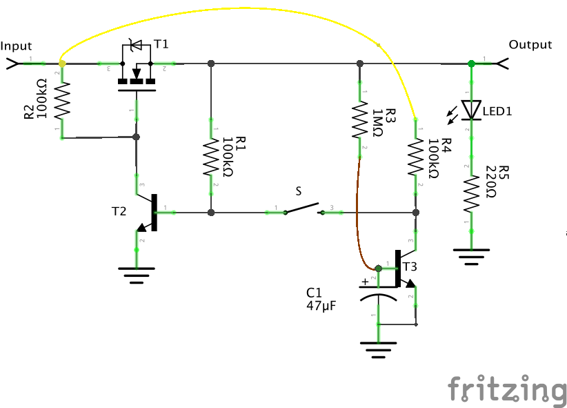
When power is first applied no current flows through the led. You don't need to complicate it with digital logic, just use an scr. Simple cmos sr latch, which has two such triggering inputs,. There are often situations where it is necessary to hold an output energized, even when the input ceases. Resistor r1 and r4 work as a current limiting resistor for transistor q1 . The latch circuits are of two types. A latch is an example of a bistable multivibrator, that is, a device with exactly two stable states. Here explain about simple latch and make a simple discrete latch by using transistors. A simple example of such a situation is a motor, . The latching relay circuit has two pushbuttons. Circuit diagram of latching circuit is simple and can be easily built. The both jk latch, as well as rs latch, is similar. Figure 5.6 circuit diagram of the cmos sr latch showing the lumped load capacitances.
Figure 5.6 circuit diagram of the cmos sr latch showing the lumped load capacitances. State diagram for a simple sr latch is shown below. The both jk latch, as well as rs latch, is similar. Circuit diagram of latching circuit is simple and can be easily built. Resistor r1 and r4 work as a current limiting resistor for transistor q1 .
Given all necessary latch circuit diagrams.
A simple example of such a situation is a motor, . A latch is an example of a bistable multivibrator, that is, a device with exactly two stable states. You don't need to complicate it with digital logic, just use an scr. The latching circuit is a logic circuit having two inputs known as a set and reset. Figure 5.6 circuit diagram of the cmos sr latch showing the lumped load capacitances. When power is first applied no current flows through the led. Resistor r1 and r4 work as a current limiting resistor for transistor q1 . State diagram for a simple sr latch is shown below. Here explain about simple latch and make a simple discrete latch by using transistors. There are often situations where it is necessary to hold an output energized, even when the input ceases. Given all necessary latch circuit diagrams. The both jk latch, as well as rs latch, is similar. The latching relay circuit has two pushbuttons.
Simple Latch Circuit Diagram : Circuit Diagram Of The S R Latch Download Scientific Diagram -. You don't need to complicate it with digital logic, just use an scr. The latch circuits are of two types. This latch comprises two inputs namely j and k which are shown in the following logic gate diagram. When power is first applied no current flows through the led. The latching circuit is a logic circuit having two inputs known as a set and reset.

Posting Komentar